In this project, you will program the MBot-Omni to autonomously navigate to a goal while avoiding obstacles.
Read these instructions for:
Getting the Code
To get the template code for this project, see your course page for the GitHub Classroom assignment link.
Once you have accepted the assignment, which will create a GitHub repository for your project code, you will need to get the code onto the robot. You will be cloning the repository on the robot's Raspberry Pi. See the robot tutorial for instructions on how to open a remote VSCode session connected to the robot. Once you are connected to the robot, in VSCode, open a terminal. This should be a terminal in the robot's Raspberry Pi. Then, clone the repository in the home directory:
git clone <ADDRESS>Substitute <ADDRESS> with the Git address for your repository found on GitHub. Open the folder of the repository you just cloned in VSCode using the instructions in the tutorial.
You should always sign the license for your code by editing the file LICENSE.txt. Replace <COPYRIGHT HOLDER> with the names of all teammates, separated by commas. Replace <YEAR> with the current year.
-
P2.0:
In the file
LICENSE.txt, replace<COPYRIGHT HOLDER>with the names of all teammates, separated by commas. Replace<YEAR>with the current year.
Project Description
In this project, we will implement an autonomous navigation algorithm. The lectures in Module 2 describe an algorithm called the Bug Algorithm. You can implement this algorithm as describe in this lecture, or implement an algorithm of your own. An example of the bug navigation algorithm in action can be found below.
You should use the robot's odometry to get the position. You may reuse your wall follower algorithm from Project 1. To program the robot, we will use the MBot Bridge API.
Robot Hits the Spot
The first step is to navigate to a given goal position and angle. In Project 1.1, we wrote a program that drove in a square by sending velocity commands to the robot. The square was not very accurate because we had no way of checking whether the robot had acheived the desired position.
Now, we will use the robot's
-
P2.1 Robot Hits the Spot:
Write an algorithm that drives the robot to a desired goal pose.
You should implement this algorithm in the function
driveToPose()in the filehit_the_spot.cppdrive_to_pose()in the filehit_the_spot.py. To get full points for this task, you should demo your robot driving to a series of goals given by course staff. Print the robot's pose after each goal has been reached.
Once we can drive to a goal location, we must encorporate avoiding obstacles. You should develop an algorithm using a State Machine (see Module 2).
Your algorithm should start by determining which state to be in. For example, if the path to the goal is obstructed, the robot should avoid the obstacle.
- P2.2: Write out your autonomous navigation algorithm and submit it to course staff. Consider using pseudocode and state machine diagrams to describe in detail how the algorithm will work.
- P2.3: Write code to determine the state of the robot at each iteration and print the current state to the screen. Course staff should be able to read the output to ensure your bug navigation is correctly transitioning between states.
- Hint: You can keep track of the state of the robot using an integer, like we did in class.
Detecting Obstacles
In Project 1, we wrote a function to find the minimum ray in the Lidar scan. This time, we want to know if there is an obstacle along the path to the goal. We can use the same minimum ray technique to do this, with some modification.
Consider the example in the photo below. We only need to check whether there is an obstacle in the direction we need to drive to get to the goal, shown by the orange arrow. But, we will want to check the rays in the slice around this arrow too, in case there is an obstacle not quite along the ray, like in the photo. We can look at the minimum ray in the slice around the direction we want to travel to determine whether the path is obstructed. In this example, the pink ray is the shortest. If this ray is too short, we will want to switch to obstacle avoidance mode.
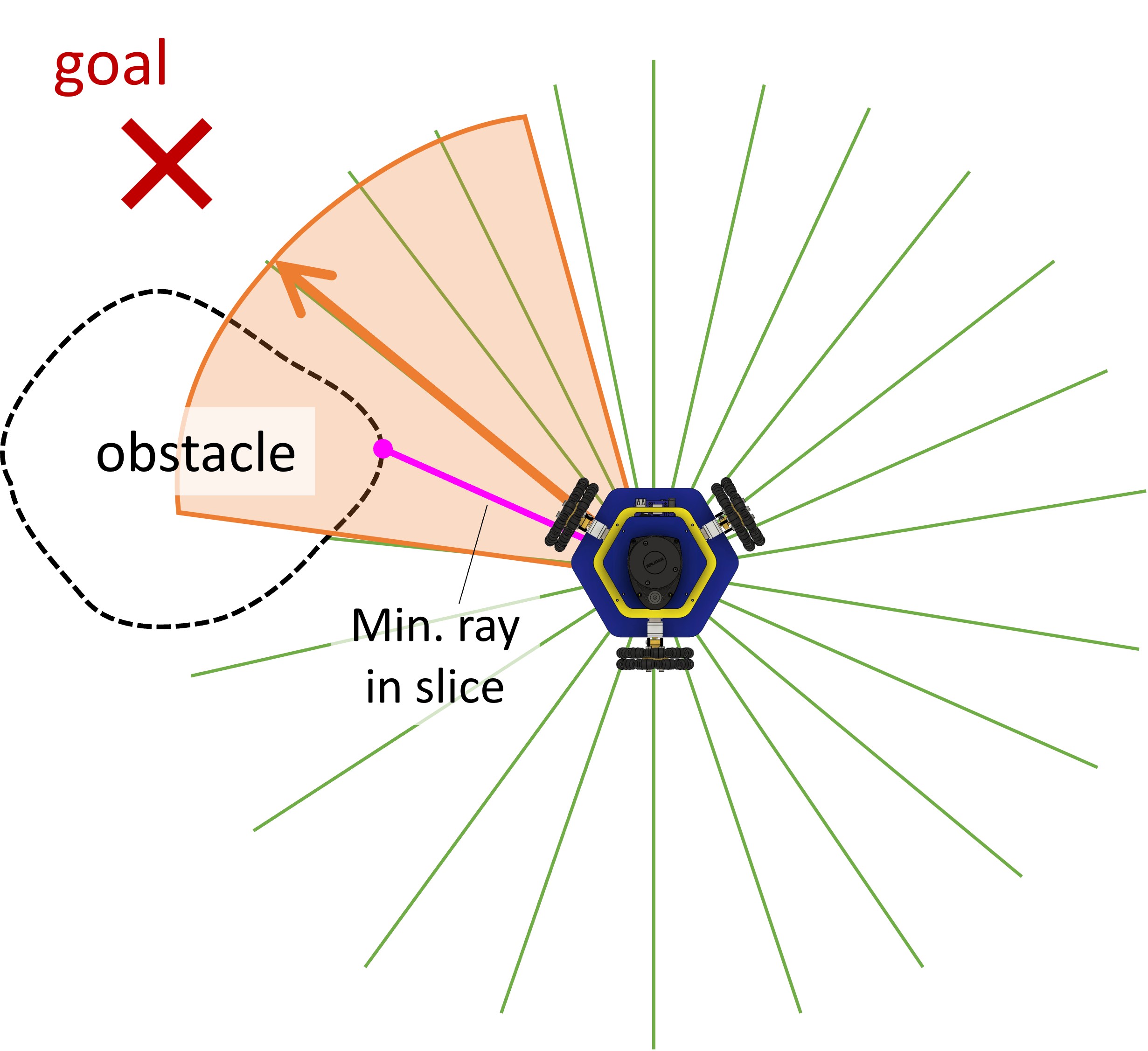
The template code includes a function findMinRayInSlice() which will tell us the minimum ray in a specific slice of the Lidar scan. You may use this function to determine whether there is an obstacle in the direction of the goal.
-
Hint: We have provided the function
findMinRayInSlice()which finds the index of the minimum ray in a slice of the Lidar scan. The function is defined as follows:int findMinDistInSlice(const std::vector& ranges, const std::vector & thetas, float target_angle, float slice_size) The function takes in the Lidar ranges and angles, and the target angle and slice size. It returns the index of the minimum ray in the slice. The slice encompasses rays within
slice_sizeradians oftarget_angle. See below:Hint: You may want to write a function
find_min_ray_in_slice()which takes in the Lidar rangles and angles, and the target angle and slice size, and finds the minimum ray in the slice, like below: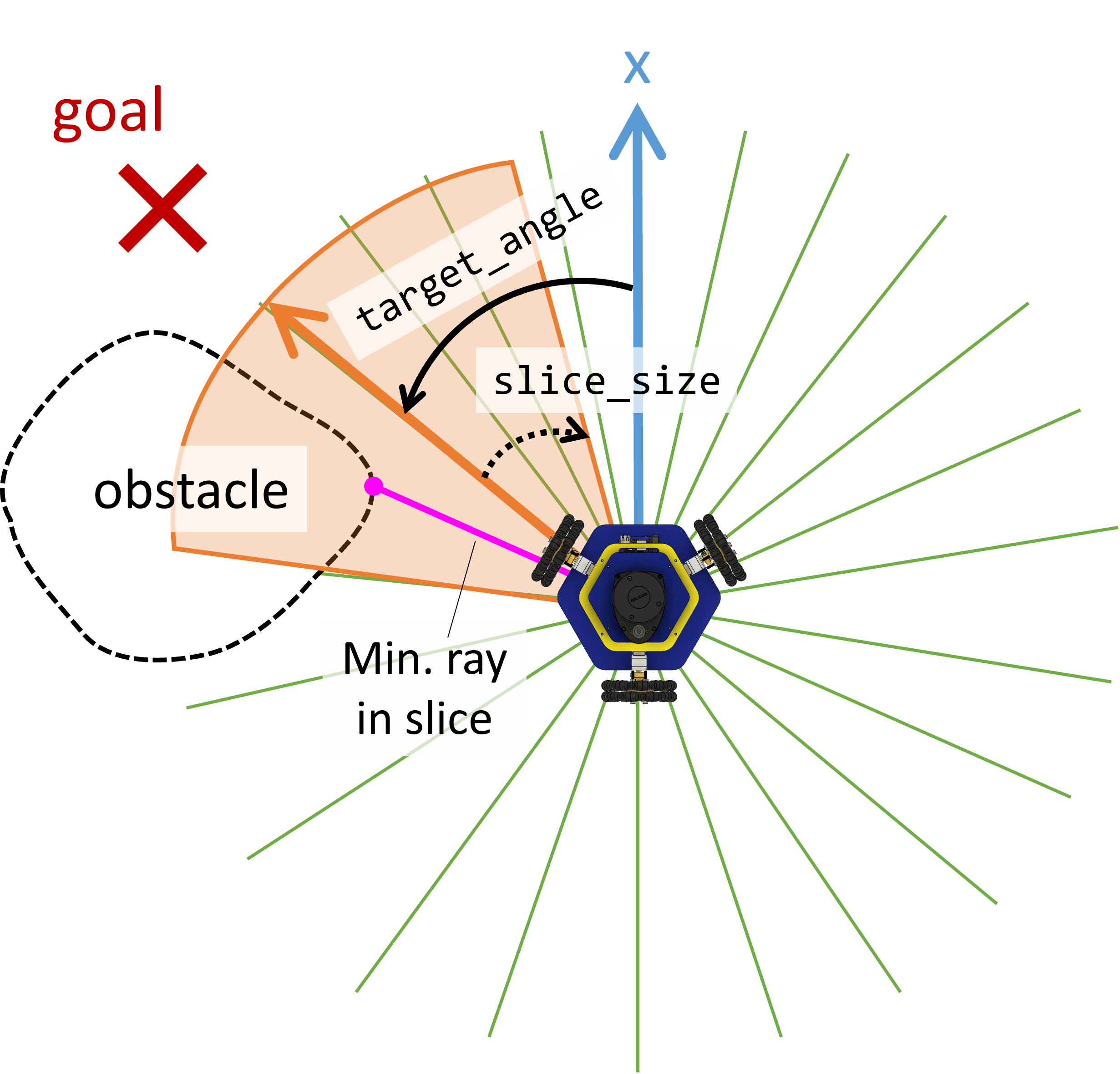
You should now have the tools to complete your bug navigation.
Write your algorithm in the file bug_navigation.cppbug_navigation.py.
The code should ask the user for x, y, and theta values for the goal, and drive to the given pose.
-
P2.4 Bug Navigation Demo:
In the file
bug_navigation.cppbug_navigation.py, write a program that drives to a goal location and avoids obstacles following the procedure outlined above. For full points, your robot will need to drive to a goal given by course staff. Staff will test 2-3 runs of your bug navigation.
Code Overview
For Project 2, we will compile and run our code the same way as in Project 1. To build the code, in a terminal, type:
cd ~/[my-bug-nav-dir]/build
cmake ..
make
Remember that the code should be cloned and compiled on the Raspberry Pi. This will fail on your computer!
You should replace [my-bug-navigation-dir] with the name of your bug navigation directory.
For a review of what these commands do, see the Project 1 description.
Repository structure
The repository includes the following dirctories and files:
-
build: Build files and executables should be generated here. All commands to compile code should be executed inside this directory. The contents are not pushed to GitHub. -
include: Header files are stored in this directory. These allow us to include code written in separate files in our code. -
src: Source code and executables are stored here. All your changes should be in this folder. -
CMakeLists.txt: Instructions for CMake to use to find dependencies and compile executables.
Provided functions
To use provided functions, all you need to do is include the correct header file. The needed header files should already be included in the templates. Also refer to the MBot Bridge API to learn how to control the robot and read its sensor data. The following functions are provided in this repo:
-
void sleepFor(float secs): Sleep for a given number of seconds. -
float wrapAngle(float angle): Wrap an angle in the range [-pi, pi]. This function returns the wrapped angle. -
int findMinDistInSlice(const std::vector: Finds the index of the minimum ray in the scan in the slice around& ranges, const std::vector & thetas, float target_angle, float slice_size) target_angleof widthslice_size. See Detecting Obstacles for more details.
The Python code contains two files where you should write your code:
-
hit_the_spot.py: The template where you will complete the Hit the Spot task, part 1 of this project. -
bug_navigation.py: The template where you will complete the Bug Navigation.
You should use the MBot Bridge API to control the robot and read data.
- Hint: You may reuse any provided function from Project 1 that you find useful.
Task Summary
-
P2.0:
In the file
LICENSE.txtincluded in the project template, replace<COPYRIGHT HOLDER>with your name. Replace<YEAR>with the current year. -
P2.1 Robot Hits the Spot Demo:
Write an algorithm that drives the robot to a desired goal pose.
You should implement this algorithm in the function
driveToPose()in the filehit_the_spot.cppdrive_to_pose()in the filehit_the_spot.py. To get full points for this task, you should demo your robot driving to a series of goals given by course staff. Print the robot's pose after each goal has been reached. - P2.2: Write out your autonomous navigation algorithm and submit it to course staff. Consider using pseudocode and state machine diagrams to describe in detail how the algorithm will work.
- P2.3: Determine the state of the robot at each iteration and print the current state to the screen. Course staff should be able to read the output to determine whether your bug navigation is correctly transitioning between states.
-
P2.4 Bug Navigation Demo:
In the file
bug_navigation.cppbug_navigation.py, write a program that drives to a goal location and avoids obstacles following the procedure outlined above. For full points, your robot will need to drive to a goal given given by course staff. Staff will test 2-3 runs of your bug navigation. -
P2.5 Project Webpage:
Create a web page for your bug navigation project including at least one video demonstration and a discussion.
Add a link to the website to the
README.mdfile in your repository.
Advanced Extensions
If you want to go further, try implementing the Bug 1 or Bug 2 algorithm, as discussed in lecture.